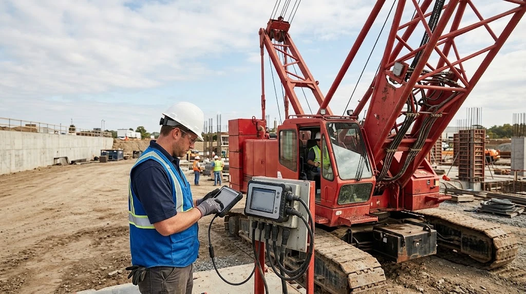
When a Manitowoc crane stops working, the Moment Control System often gets attention first. This system, also known as the Load Moment Indicator, protects the crane from unsafe lifting conditions. Understanding its parts and behavior helps technicians diagnose problems faster. This guide reviews system generations, common failures, and replacement options.
MCS Fundamentals
The Moment Control System calculates safe working load from boom length, angle, and radius. It uses electronic sensors and a controller to compare actual conditions against a stored load chart. If the lift exceeds safe limits, the system interrupts the lifting functions. That action helps prevent tipping and structural damage.
The system operates in harsh conditions. Sensors face vibration, moisture, and temperature swings. Wiring can rub against metal edges. Connectors can corrode. These conditions explain why periodic inspection matters. A small fault can grow into a lockout.
Determining Your System Generation
Manitowoc has used several LMI designs across its crane families. Older machines may carry the EPIC system. Newer units often use CRCS or CAN-bus architectures. Each design performs similar safety functions. Their communication methods differ significantly.
Older systems often run dedicated wires from each sensor to the controller. Newer systems share data over a network. That network connects controllers, displays, and sensors. Troubleshooting steps differ between the two approaches. Testing a digital sensor requires different tools than testing an analog one.
Knowing the generation prevents wasted effort. It also helps when ordering components. A part that fits one generation may not fit another.
LMI Components Most Likely to Fail
Several components within the MCS are prone to wear. Recognizing them helps narrow down a fault. The list below covers the most frequent trouble spots.
Length and Angle Sensors: These units mount near the boom head. They report boom tip position to the controller. An angle sensor may use a pendulum or inclinometer. Weather, dirt, and vibration affect its accuracy.
A length sensor uses a mechanical reeling system, and its cable can stretch, break, or wear. If the controller receives a false boom length, the load chart becomes incorrect. These crane parts endure constant movement, which eventually causes wear.
Pressure Transducers: These devices measure hydraulic pressure to estimate load weight. They connect to the hoist cylinders. Moisture, shock, or age can cause failure. When they fail, load readings may become erratic.
The Controller: This unit acts as the system’s brain. It receives sensor signals and compares them to stored load charts. Then it sends commands to the display and cutoff valves. Controllers rarely fail without cause, but water intrusion or short circuits can damage them quickly.
Displays and HMI: The cab display shows critical lifting information. Backlights can burn out, screens can crack, and buttons can stop responding. If the operator cannot read the display, safe operation becomes difficult.
Early Indicators of a Problem
An LMI does not always fail with a clear error code. Sometimes readings jump around. Load weight may bounce by several thousand pounds while the load is stationary, and boom angle may drift by a few degrees. These symptoms deserve attention.
Operators often notice subtle changes before a full failure. If an operator reports unusual behavior, investigate promptly. Waiting can lead to a lockout on the job site.
Start with basic checks. Inspect wires near the boom hinge for chafing. Look inside junction boxes for moisture. Corroded crane parts and connections cause many apparent sensor failures. Cleaning or replacing a connector may solve the issue.
Sourcing Replacement Components
When a component fails, replacement speed matters. Correct selection matters just as much. The wrong component can waste time and create new safety concerns. Use the following guidelines to improve outcomes.
OEM and Aftermarket Options
Original Equipment Manufacturer components are built for specific crane models. Genuine Manitowoc parts match the system’s electrical and software requirements. They reduce compatibility risk in safety-critical applications. Aftermarket alternatives exist, but quality varies.
Some Manitowoc parts from aftermarket sources may work correctly. Others may not meet output specifications. A pressure transducer with the wrong milliamp output can produce inaccurate load readings. Buy from suppliers who understand crane electronics and ask about warranty and return policies.
The Role of Serial Numbers
Manitowoc updates systems over time. A 2012 crane may have a different LMI setup than a 2016 model. The crane model name alone does not guarantee compatibility. Serial numbers and old part numbers provide the details needed.
Record the crane serial number before calling a dealer. Also note the part number from the failed component. This information helps confirm the correct replacement. It also reduces the chance of ordering the wrong item.
Firmware and Software Considerations
Hardware replacement is only part of the repair. Controllers require correct firmware to read sensors properly. A used controller may not arrive with the right software. A Manitowoc dealer may need to load load charts and configuration files.
Do not assume a replacement controller will plug and play. Even genuine Manitowoc parts may need programming. Confirm software requirements before installation. That step prevents delays after the part arrives.
When Parts Are No Longer Available
Dealers sometimes report that a component is obsolete. This situation is common with older cranes. The original sensor may be out of production. Several options remain available.
You can search for rebuilt or used crane parts online. Verify the seller’s reputation and the part’s condition. Ask for test results when possible. Another option is a retrofit kit.
Manitowoc and some third-party companies offer upgrade kits. These kits replace older analog sensors with digital equivalents. They may cost more upfront, but they can simplify future maintenance and improve diagnostic capabilities. Some rebuilders specialize in Manitowoc parts for discontinued systems.
Installing and Calibrating Electronic Safety Components
Mechanical installation is often straightforward. Electrical work requires care. Follow these practices to avoid damaging new components.
Disconnect the Power: Remove battery power before unplugging or connecting electronic parts. Hot-swapping can destroy a new controller instantly. This simple step protects the equipment.
Protect the Connections: LMI connectors use small pins that carry low-voltage signals. A bent pin, dirt, or moisture can cause intermittent faults. Use dielectric grease to keep water out. Take time when mating connectors.
Route Cables Carefully: Length sensor cables must follow factory routing. A cable rubbing a sharp edge can chafe through quickly. Use proper ties and guides. Poor routing can cause repeat failures.
Calibration Is Mandatory: A new angle sensor cannot simply be bolted on and used. The system requires calibration. Certified test weights and a calibrated angle gauge are needed. Skipping calibration compromises safety and puts the crew at risk.
Recordkeeping Practices
After repairs, document the work performed. Record the part numbers used and calibration values entered. Note the date and the technician’s name. Keep this log with the crane’s maintenance records.
This record saves time during future diagnostics. It also helps the next technician understand prior repairs. A clear history supports better maintenance decisions.
Closing Thoughts
The Manitowoc Moment Control System is a vital safety layer. When it fails, repair pressure is high. Avoid rushing the process. Diagnose the exact failure before ordering components.
Use the correct parts and calibrate the system afterward. Keep accurate records for future reference. These steps help return the crane to safe service. They also support longer periods of reliable operation.
Comments
No comments yet. Be the first to react!